Track Circuit Diagram
TRACK CIRCUIT OPERATION
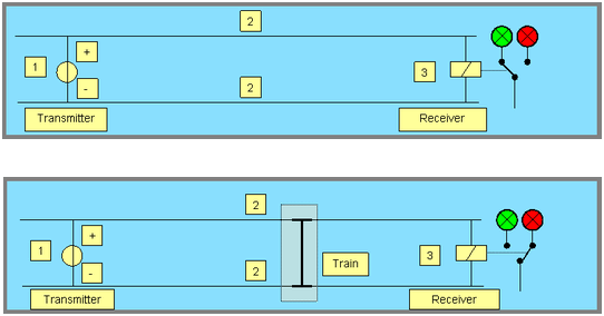
Railway safety systems are in many cases based on track circuits. The track is divided in electrical sections. In each section a signal transmitter [1] is connected to the rails [2] on one end. A signal receiver [3] is connected on the other end. When no train is present the receiver can detect the signal that is applied to the rails by the transmitter. The wayside signal indicates non-occupancy of the track circuit. It shows green. When a train is present, the electrically conductive axles of the train short circuit the running rails. The signal from the transmitter can no longer be detected by the receiver. The way-side signal now shows that the track circuit is occupied. It switches from green to red.
Railway safety systems are in many cases based on track circuits. The track is divided in electrical sections. In each section a signal transmitter [1] is connected to the rails [2] on one end. A signal receiver [3] is connected on the other end. When no train is present the receiver can detect the signal that is applied to the rails by the transmitter. The wayside signal indicates non-occupancy of the track circuit. It shows green. When a train is present, the electrically conductive axles of the train short circuit the running rails. The signal from the transmitter can no longer be detected by the receiver. The way-side signal now shows that the track circuit is occupied. It switches from green to red.

